
Page 460 - Softbound_Edition_19_en
P. 460
A
85
45 1 E 2 40 3 4 19.5 h8 5 A
B B
15 14 12 11
30 50* 20 13 16 10
MD= 9.5Nm MD= 5.2 Nm 55 29
Poppet valve cartridge
64
Poppet valve cartridges Poppet valve cartridges 31
4
74
C C
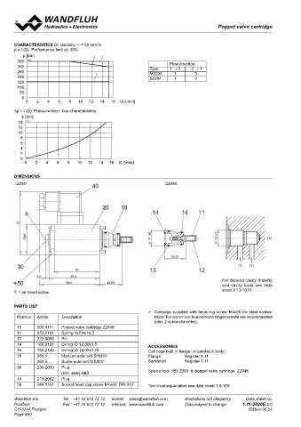
cHARActeRIStIcS Oil viscosity υ = 30 mm /s Solenoid poppet valve cartridge
2
p = f (Q) Performance limit at -10% • normally closed
p [bar] 2 1 • Q = 40 l/min NG6
350 K0160 Flow direction • p max = 350 bar
300 Type 1 → 2 2 → 1 max Gezeichnet 28.10.2016 BEH
250 M2204 3 3 D Rev. Datum Name Änderungsnr. Änderungsbeschrieb Geprüft M 1:1 15.11.2016 MM BR D
15.02.2017
Freigegeben
Serie freigegeben
Gewicht
200 3 S2204 1 2 Magnet-Sitzventilpatrone NG6 Ersetzt durch: 0.238 kg
Ersatz für:
Dok.-Nr.
.2206
Format
0208202
A3
150 Dokument darf ohne schriftliche Einwilligung weder kopiert, Art.-Nr. DB 1.11-2030 Revision
00
verwertet noch an Dritte weitergegeben werden.
100 DESCRIPTION FUNCTION APPLICATION 1 2 Zuwiderhandlung ist strafbar und wird gerichtlich verfolgt. Blatt 1 von 1
C:\00_Wandfluh\Verkauf\Dokumentation\Reg1.11\DB 1.11-2030\0208202
50 The 2/2-way seating valve in slip-in cartridge The seating valve piston is held against the Wandfluh poppet valves can be used any-
0 form is the central control element of virtually spring by the pressure-tight control solenoid. where absolutely leak tight closing functions
0 2 4 6 8 10 12 14 16 Q [l/min] all directly-controlled seating valves in nominal Because the seat-piston design has equal are important. Completely sealed loading,
size 6. The seating valve cartidge, the stroke surface areas on both sides and since the gripping and clamping operations are all impor-
∆p = f (Q) Pressure loss / flow characteristics limiting piston, the spring, one O-ring and a seat / piston construction is balanced in terms of tant functions which Wandfluh poppet valves
p [bar] washer are supplied separately. A solenoid pressure, no undesirable closing and opening can perform. Cartridge typ poppet valves can
14 K0161 (VDE standard 0580) is an optional addition. forces are generated. As a result, oil can flow in be neatly accommodated in valve blocks.
12 Important: at the time the valve is taken into both directions through the seating valve. The Cavity tools are available for hire or sale for
10 service, the valve must be vented under pres- seat / piston guide is sealed with an O-ring. The machining aluminium or steel. See data sheet
8 sure (max. 2 revolutions of screw E). seat with a metallic seal closes off the valve so register no. 2.13.
6 that there is no leakage oil.
4
2 TYPE CODE
0 Poppet valve cartridge 2 2 06 #
0 2 4 6 8 10 12 14 16 Q [l/min] Poppet valve cartridge with solenoid 2 2 06 - #
Medium-solenoid M
dIMeNSIoNS
Super-solenoid S
. 2204- . . 2204K
2-way (Connections)
2 Positions
Nominal size 6
Nominal voltage U 12 VDC G12 110 VAC R110
N
24 VDC G24 115 VAC R115
230 VAC R230
Design-Index (Subject to change)
GENERAL SPECIFICATIONS ELECTRICAL CONTROL
Description 2/2-way poppet valve cartridge Construction Solenoid, wet pin push, pressure tight
Nominal size NG6 Standard-nominal flow U = 12 VDC, 24 VDC
N
Construction Direct operated poppet valve U = 110 VAC∗, 115 VAC∗, 230 VAC∗
N
Operations Solenoid AC = 50 to 60 Hz
Mounting cartrigde form ∗ Rectifier integrated in the plug
For detailed cavity drawing 4 solenoid fixing screws M5 Other nominal voltages and nominal
and cavity tools see data Ambient temperature -20…+50 °C performances on request
sheet 2.13-1013
E = air bleed screw Mounting position any Voltage tolerance ±10% of nominal voltage
Fastening torque M = 5,2 Nm (quality 8.8) Protection class IP 65 to EN 60 529
D
Weight: 2206 m = 0,04 kg Relative duty factor 100% DF (see data sheet 1.1-430)
pARtS LISt . 2206- . . m = 0,8 kg Switching cycles 15 000/h
∗ Cartridge supplied with fastening screw M4x60 for steel bodies/ Volume flow direction any Operating life 10 (number of switching cycles, theoretically)
7
Position Article Description blocs. For aluminium bodies/blocs longer screws are recommended Connections / Power supply Over device plug connection to
(min. 2 screw diameter). ISO 4400 / DIN 43650, (2P+E),
10 500.9111 Poppet valve cartridge 2204K HYDRAULIC SPECIFICATIONS other connections on request
11 053.2101 Spring 1x7,4x16,5 Fluid Mineral oil, other fluid on request Solenoid: – Medium SIN45V (1.1-120)
12 222.0056 Pin Contamination efficiency ISO 4406:1999, class 20/18/14 – Super SIS45V (1.1-125)
14 160.2121 O-ring ID 12,00x1,5 AcceSSoRIeS (Required filtration grade ß10…16≥75)
refer to data sheet 1.0-50/2
15 160.2140 O-ring ID 14,00x1,78 Cartridge built-in flange- or sandwich body: Viscosity range 12 mm /s…320 mm /s
2
2
20 260.4… Medium-solenoid SIN35V Flange Register 1.11 Fluid temperature -20…+70 °C SYMBOLS
260.5… Super-solenoid SIS35V Sandwich Register 1.11 Working pressure Medium: p max = 160 bar 2206 . 2206- . .
30 239.2033 Plug Super: p max = 350 bar
(incl. seal) HB0 Special tool 983.2000 to poppet valve cartridge 2204K Max. volume flow Q max = 40 l/min, see characteristics
40 219.2002 Plug
50 246.1161 Socket head cap screw M4x60 DIN 912 Technical explanation see data sheet 1.0-100
Wandfluh AG Tel. +41 33 672 72 72 E-mail: [email protected] Illustrations not obligatory Data sheet no. Wandfluh AG Tel. +41 33 672 72 72 E-mail: [email protected] Illustrations not obligatory Data sheet no.
Postfach Fax +41 33 672 72 12 Internet: www.wandfluh.com Data subject to change 1.11-2020E 2/2 Postfach Fax +41 33 672 72 12 Internet: www.wandfluh.com Data subject to change 1.11-2030E 1/2
CH-3714 Frutigen Edition 06 51 CH-3714 Frutigen Edition 21 35
Page 460