
Page 472 - Softbound_Edition_19_en
P. 472
Poppet valve
Poppet valve cartridge Poppet valve
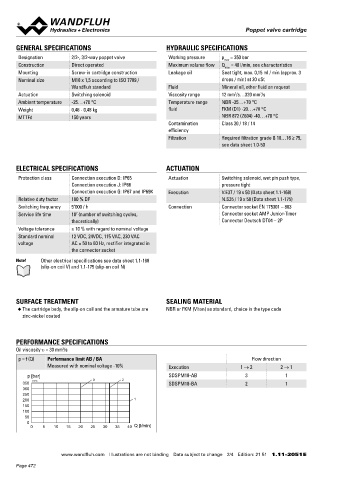
GENERAL SPECIFICATIONS HYDRAULIC SPECIFICATIONS PERFORMANCE SPECIFICATIONS
2
Designation 2/2-, 3/2-way poppet valve Working pressure p = 350 bar Oil viscosity u = 30 mm /s
max
Construction Direct operated Maximum volume flow Q = 40 l/min, see characteristics p = f (Q) Performance limit FG Flow direction
max
Mounting Screw-in cartridge construction Leakage oil Seat tight, max. 0,15 ml / min (approx. 3 Measured with nominal voltage -10% Execution 1 → 2 2 → 1 2 → 3 3 → 2
Nominal size M18 x 1,5 according to ISO 7789 / drops / min) at 30 cSt p [bar] SDSPM18-FG 3 1 1 2
Wandfluh standard Fluid Mineral oil, other fluid on request 350 K4239 3 2
Actuation Switching solenoid Viscosity range 12 mm /s…320 mm /s 300
2
2
Ambient temperature -25…+70 °C Temperature range NBR -25…+70 °C 250 1
Weight 0,46 - 0,48 kg fluid FKM (D1) -20…+70 °C 200
150
MTTFd 150 years NBR 872 (Z604) -40…+70 °C 100
Contamination Class 20 / 18 / 14 50
efficiency 0 0 2,5 5 7,5 10 12,5 15 17,5 20 Q [l/min]
Filtration Required filtration grade ß 10…16 ≥ 75,
see data sheet 1.0-50
∆p = f (Q) Pressure drop volume flow characteristics Flow direction
∆p [bar] Execution 1 → 2 2 → 1 2 → 3 3 → 2
ELECTRICAL SPECIFICATIONS ACTUATION 30 K4240 1 SDSPM18-AB 4 4 - -
25 SDSPM18-BA 3 3 - -
Protection class Connection execution D: IP65 Actuation Switching solenoid, wet pin push type, 20 2
Connection execution J: IP66 pressure tight 15 SDSPM18-FG 2 2 1 1
Connection execution G: IP67 and IP69K Execution V.E37 / 19 x 50 (Data sheet 1.1-168) 10 3 4* *∆p 80 bar at 40 l/min
Relative duty factor 100 % DF N.S35 / 19 x 50 (Data sheet 1.1-175) 5
Switching frequency 5'000 / h Connection Connector socket EN 175301 – 803 0 Q [l/min]
Service life time 10 (number of switching cycles, Connector socket AMP Junior-Timer 0 2,5 5 7,5 10 12,5 15 17,5 20
7
theoretically) Connector Deutsch DT04 – 2P
Voltage tolerance ± 10 % with regard to nominal voltage Switching times
Standard nominal 12 VDC, 24VDC, 115 VAC, 230 VAC Typ Flow Switching on Switching off
voltage AC = 50 to 60 Hz, rectifier integrated in direction
the connector socket
AB 1 → 2 approx. 40 ms approx. 20 ms
Note! Other electrical specifications see data sheet 1.1-168 2 → 1 approx. 40 ms approx. 10 ms
(slip-on coil V) and 1.1-175 (slip-on coil N) SDSPM18 BA 1 → 2 approx. 40 ms approx. 30 ms
2 → 1 approx. 30 ms approx. 30 ms
FG 1 → 2 approx. 40 ms approx. 10 ms
2 → 1 approx. 40 ms approx. 10 ms Note! The switching times depend on the volume flow,
pressure and viscosity. In case of very large volume
SURFACE TREATMENT SEALING MATERIAL 2 → 3 approx. 40 ms approx. 40 ms flows, the switching time for closing can get consider-
3 → 2
approx. 40 ms
approx. 20 ms
◆ The cartridge body, the slip-on coil and the armature tube are NBR or FKM (Viton) as standard, choice in the type code ably longer.
zinc-nickel coated
HYDRAULIC CONNECTION HYDRAULIC CONNECTION
Cavity drawing according to ISO 7789–18–01–0–98 Cavity drawing according to Wandfluh standard
PERFORMANCE SPECIFICATIONS
Oil viscosity u = 30 mm /s M18x1.5 M18x1.5
2
p = f (Q) Performance limit AB / BA Flow direction
Measured with nominal voltage -10% Execution 1 → 2 2 → 1 (3)
(2)
p [bar] SDSPM18-AB 3 1 (2)
350 K4238 3 2 SDSPM18-BA 2 1
300 (1) (1)
250
200 1 (1) (1)
150
100
50 Note! For detailed cavity drawing and cavity tools see data Note! For detailed cavity drawing and cavity tools see data
0 sheet 2.13-1002 sheet 2.13-1020
0 5 10 15 20 25 30 35 40 Q [l/min]
www.wandfluh.com Illustrations are not binding Data subject to change 2/4 Edition: 21 51 1.11-2051 E www.wandfluh.com Illustrations are not binding Data subject to change 3/4 Edition: 21 51 1.11-2051 E
Page 472