
Page 476 - Softbound_Edition_19_en
P. 476
Poppet valve
Poppet valve cartridge Poppet valve
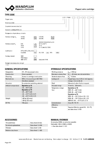
TYPE CODE ELECTRICAL SPECIFICATIONS STANDARDS
S D Y PM18 - - / - # Protection class IP65 / 66 / 67 Cartridge cavity ISO 7789 / Wandfluh standard
Poppet valve Relative duty factor 100 % DF Explosion protection Directive 2014 / 34 / EU (ATEX)
Direct operated Switching frequency 5'000 / h Flameproof enclosure EN / IEC / UL 60079-1, 31
Voltage tolerance ± 10 % with regard to nominal voltage Cable entry EN 60079-0, 1, 7, 15, 31
Ex-protection execution, Exd Standard nominal 12 VDC, 24VDC, 115 VAC, 230 VAC Protection class EN 60 529
voltage AC = 50 to 60 Hz ± 2 %, with built-in Contamination ISO 4406
Screw-in cartridge M18 x 1,5
two-way rectifier efficiency
Designation of symbols acc. to table Standard nominal 9 W, 15 W, 17 W
power
Nominal voltage U 12 VDC G12 115 VAC R115 Temperature class Nominal power 9 W: T1…T6
N
24 VDC G24 230 VAC R230
Nominal power 15 W / 17 W: T1…T4
Ambient temperature up to: Note! Other electrical specifications see data sheet 1.1-183
Nominal power P 9 W L9 40 °C or 90 °C and 1.1-184
N
15 W L15 70 °C
17 W L17 70 °C (only UL / CSA)
Certification ATEX, IECEx, EAC, CCC
Australia AU UL / CSA UL MA MA INSTALLATION NOTES COMMISSIONING
Mounting type Screw-in cartridge M18 x 1,5 Attention! When commissioning, the valve must be vented under
Sealing material NBR pressure (max. two rotations of screw E).
FKM (Viton) D1 Mounting position Any, preferably horizontal
NBR -40° C Z604 (only with 15 W) Tightening torque M = 40 Nm Screw-in cartridge
D The solenoid coil must only be put into operation, if the
M = 5 Nm knurled nut requirements of the operating instructions supplied are
D
Design index (subject to change) M = 9,5 Nm HB0
1.11-2052 D observed to their full extent. In case of non-observance,
M = 5,5 Nm HB4,5 no liability is assumed.
D
GENERAL SPECIFICATIONS HYDRAULIC SPECIFICATIONS
Designation 2/2-, 3/2-way poppet valve Working pressure p = 350 bar
max
Construction Direct operated Maximum volume flow Q = 20 l/min, see characteristics PERFORMANCE SPECIFICATIONS
max
Mounting Screw-in cartridge construction Nominal volume flow Q = 15 l/min Oil viscosity u = 30 mm /s
2
N
Nominal size M18 x 1,5 according to ISO 7789 / Leakage oil Poppet type, max. 0,15 ml / min (approx. p = f (Q) Performance limit AB / BA Flow direction
Wandfluh standard 3 drops / min) at 30 cSt Measured with nominal voltage -10% at 50 °C Execution 1 → 2 2 → 1
Actuation Ex-protection switching solenoid Fluid Mineral oil, other fluid on request
Ambient temperature Operation as T6 Viscosity range 12 mm /s…320 mm /s p [bar] 1 2 SDYPM18-AB 1 3
2
2
K4243
-25…+40 °C (L9) Temperature range Operation as T6 350 SDYPM18-BA 2 2
300
Operation as T4 fluid NBR -25…+40 °C (L9) 250 3
-25…+90 °C (L9) FKM -20…+40 °C (L9) 200
-25…+70 °C (L15 / L17) Operation as T4 150
-40…+70 °C (L15 / L17) NBR -25…+70 °C (L9 or L15 / L17) 100
Weight 1,85 kg (2/2-way) FKM -20…+70 °C (L9 or L15 / L17) 50 0
1,90 kg (3/2-way) NBR 872 -40…+70 °C (L15 / L17) 0 5 10 15 20 Q [l/min]
MTTFd 150 years Contamination Class 20 / 18 / 14
efficiency
Filtration Required filtration grade ß 6…10 ≥ 75, p = f (Q) Performance limit FG Flow direction
see data sheet 1.0-50 Measured with nominal voltage -10% at 50 °C Execution 1 → 2 2 → 1 2 → 3 3 → 2
p [bar] 1 2 SDYPM18-FG-L9 4 1 2 5
350 K4244 SDYPM18-FG-L15 / L17 4 1 1 3
300
250
ACCESSORIES MANUAL OVERRIDE 200 3
Threaded body Data sheet 2.9-2xx Screw plug (HB0), no actuation possible 150 4
100
Optionally: HB4,5, HN(K) or HG(K) 5
Technical explanations Data sheet 1.0-100 → See data sheet 1.1-311 50
Filtration Data sheet 1.0-50 0 0 2,5 5 7,5 10 12,5 15 17,5 20 Q [l/min]
Relative duty factor Data sheet 1.1-430
www.wandfluh.com Illustrations are not binding Data subject to change 2/5 Edition: 21 18 1.11-2052 E www.wandfluh.com Illustrations are not binding Data subject to change 3/5 Edition: 21 18 1.11-2052 E
Page 476