Page 501 - Softbound_Edition_19_en
P. 501

Poppet valve
                                                                                             Poppet valve cartridge


            PERFORMANCE SPECIFICATIONS
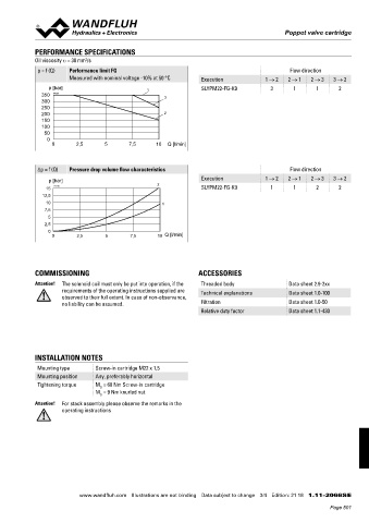
            Oil viscosity u = 30 mm /s
                             2
             p = f (Q)  Performance limit FG                                                   Flow direction
                       Measured with nominal voltage -10% at 50 °C  Execution          1 → 2  2 → 1  2 → 3   3 → 2
                 p [bar]                        1                 SLYPM22-FG-K9         3       1      1      2
              350  K4235                              3
              300
              250
              200                                     2
              150
              100
               50
                0
                  0       2,5      5       7,5     10  Q [l/min]


             ∆p = f (Q)  Pressure drop volume flow characteristics                             Flow direction

                 p [bar]                                          Execution            1 → 2  2 → 1  2 → 3   3 → 2
                15  K4236                           2             SLYPM22-FG-K9         1       1      2      2
               12,5
                10                                   1
               7,5
                 5
               2,5
                 0
                  0       2,5      5       7,5      10  Q [l/min]


            COMMISSIONING                                        ACCESSORIES
            Attention!    The solenoid coil must only be put into operation, if the   Threaded body  Data sheet 2.9-2xx
                     requirements of the operating instructions supplied are   Technical explanations  Data sheet 1.0-100
                     observed to their full extent. In case of non-observance,
                     no liability can be assumed.                 Filtration                  Data sheet 1.0-50
                                                                  Relative duty factor        Data sheet 1.1-430


            INSTALLATION NOTES
             Mounting type      Screw-in cartridge M22 x 1,5
             Mounting position  Any, preferably horizontal
             Tightening torque  M  = 60 Nm Screw-in cartridge
                                 D
                                M  = 9 Nm knurled nut
                                 D
            Attention!  For stack assembly please observe the remarks in the
                     operating instructions


                           www.wandfluh.com  Illustrations are not binding  Data subject to change  3/4  Edition: 21 18  1.11-2066S E
                                                                                                            Page 501
   496   497   498   499   500   501   502   503   504   505   506