Page 504 - Softbound_Edition_19_en
P. 504

Poppet valve
                                                                                       Poppet valve cartridge                                                                                                                Poppet valve


       GENERAL SPECIFICATIONS                              ACTUATION                                                                DIMENSIONS                                          HYDRAULIC CONNECTION
       Designation        2/2-way poppet valve              Actuation          Switching solenoid, wet pin push + pull                                                                  Cavity drawing according to ISO 7789–33–01–0–98
       Construction       Pilot operated                                       type, pressure tight
       Mounting           Screw-in cartridge construction   Execution          W.E37 / 16 x 40 (Data sheet 1.1-169)                                                                                          M33 x 2
       Nominal size       M33 x 2 according to ISO 7789                        M.E35 / 16 x 40 (Data sheet 1.1-171)                                               s36  M33x2
       Actuation          Switching solenoid                Connection         Connector socket EN 175301 – 803                           76
       Ambient temperature  -25…+70 °C                                         Connector socket AMP Junior-Timer                            37                             (2)                                        (2)
       Weight             0,7 kg                                               Connector Deutsch DT04 – 2P                                                                       (1)
       MTTFd              150 years                                                                                                          W =
                                                                                                                                                                                                                      (1)
                                                                                                                                        15     12  17 10         50  40 13  60   30                             (1)
       HYDRAULIC SPECIFICATIONS                            ELECTRICAL SPECIFICATIONS                                                MD= 9.5Nm  MD= 5Nm     64             50
       Working pressure   p   = 350 bar                     Protection class   Connection execution D: IP65                                                      118                    Note!    For detailed cavity drawing and cavity tools see data
                           max                                                                                                                                                                   sheet 2.13-1005
       Opening pressure   1,5 bar 1 → 2 version CB / BC                        Connection execution J: IP66
                          2,5 bar 1 → 2 version AB / BA                        Connection execution G: IP67 and IP69K
                          2,5 bar 2 → 1 version AB / BA     Relative duty factor  100 % DF, W.E37 only up to 50 °C
       Maximum volume flow  Q   = 150 l/min, see characteristics  Switching frequency  5'000 / h                                                                                        STANDARDS
                            max
       Leakage oil        Poppet type, max. 0,15 ml / min (approx.   Service life time  10  (number of switching cycles,                     75                                          Cartridge cavity   ISO 7789
                                                                                7
                          3 drops / min) at 30 cSt                             theoretically)                                                                                            Solenoids          DIN VDE 0580
       Fluid              Mineral oil, other fluid on request  Voltage tolerance  ± 10 % with regard to nominal voltage                       35                                         Connection execution D  EN 175301 – 803
       Viscosity range    12 mm /s…320 mm /s                Standard nominal   12 VDC, 24VDC, 115 VAC, 230 VAC                                 M =                                       Protection class   EN 60 529
                                        2
                               2
       Temperature range   -25…+70 °C (NBR)                 voltage            AC = 50 to 60 Hz, rectifier integrated in                                                                 Contamination efficiency ISO 4406
       fluid              -20…+70 °C (FKM)                                     the connector socket                                                 10
       Contamination      Class 20 / 18 / 14               Note!    Other electrical specifications see data sheet 1.1-169
       efficiency                                                   (slip-on coil W) and 1.1-171 (slip-on coil M)
       Filtration         Required filtration grade ß 10…16 ≥ 75,                                                                                                                       ACCESSORIES
                          see data sheet 1.0-50                                                                                      Position Article  Description                       Threaded body               Data sheet 2.9-2xx
                                                                                                                                         10 206.2...  W.E37 / 16 x 40                    Technical explanations      Data sheet 1.0-100
       PERFORMANCE SPECIFICATIONS                                                                                                           260.4...  M.E35 / 16 x 40                    Filtration                  Data sheet 1.0-50
       Oil viscosity u = 30 mm /s                                                                                                        12 154.2600  Knurled nut M16 x 1 x 9            Relative duty factor        Data sheet 1.1-430
                       2
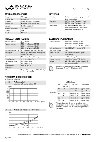
       p = f (Q)  Performance limit                                           Switching times                                            13 212.0013  Plastic disc rd 7 x 1,5
                  Measured with nominal voltage -10%                 Type    Flow      Energised  De-energised                           15 239.2033  Screw plug HB0 (incl. seal)
           p [bar]                                                          direction                                                    17 160.2156  O-ring ID 15,60 x 1,78 (NBR)
         350  K0735_1                                                 AB  1→2        approx. 100 ms approx. 60 ms                        30 160.2238  O-ring ID 23,81 x 2,62 (NBR)      INSTALLATION NOTES
         300                                                              2→1        approx. 100 ms approx. 80 ms                           160.6238  O-ring ID 23,81 x 2,62 (FMK)
         250                                                SVSPM33                                                                                                                      Mounting type      Screw-in cartridge M33 x 2
         200                                                          BA  1→2        approx. 30 ms  approx. 100 ms                       40 160.2298  O-ring ID 29,82 x 2,62 (NBR)       Mounting position  Any, preferably horizontal
         150                                                              2→1        approx. 30 ms  approx. 100 ms                          160.6296  O-ring ID 29,82 x 2,62 (FMK)       Tightening torque  M  = 130 Nm for screw-in cartridge
                                                                                                                                                                                                             D
         100                                                          BC  2→1        approx. 30 ms  approx. 70 ms                        50 160.1260  O-ring ID 26,00 x 1,00 (NBR)                          M  = 5 Nm for Knurled nut
          50                                                                                                                                                                                                 D
           0                                                          CB  2→1        approx. 60 ms  approx. 70 ms                        60 049.8297  Backup ring PTSM rd 22,1 x 26,6 x 1,4
            0   20   40   60   80  100 120 140 160  Q[l/min]
                                                            Note!   The switching times depend on the volume flow,
                                                                    pressure and viscosity. In case of very large volume
                                                                    flows, the switching time for closing can get consider-        SEALING MATERIAL                                     MANUAL OVERRIDE
                                                                    ably longer.                                                   NBR or FKM (Viton) as standard, choice in the type code  Screw plug (HB0), no actuation possible.
       ∆p = f (Q)  Pressure drop volume flow characteristics
                                                                                                                                                                                        Optionally HN (K) or HG (K) (pushing) resp. HZ (K) (pulling)
           p [bar]                                                                                                                                                                      → See data sheet 1.1-311
         20  K0736_2                                                                                                               SURFACE TREATMENT                                    Attention!  The manual override HZ (H91) cannot be retrofitted.
                                                                                                                                    ◆  The cartridge body, the slip-on coil and the armature tube are
         15
                                                                                                                                      zinc-nickel coated
         10                   AB / BA
          5
          0                   BC / CB
            0    25    50   75   100   125   150 Q [l/min]
                                                                                                                                                                                        Wandfluh AG  Postfach  CH-3714 Frutigen
                                                                                                                                                                                        Tel. +41 33 672 72 72  Fax +41 33 672 72 12  [email protected]

                       www.wandfluh.com  Illustrations are not binding  Data subject to change  2/3  Edition: 21 26  1.11-2076 E                   www.wandfluh.com  Illustrations are not binding  Data subject to change  3/3  Edition: 21 26  1.11-2076 E
       Page 504
   499   500   501   502   503   504   505   506   507   508   509