
Page 519 - Softbound_Edition_19_en
P. 519
Poppet valve
Poppet valve cartridge
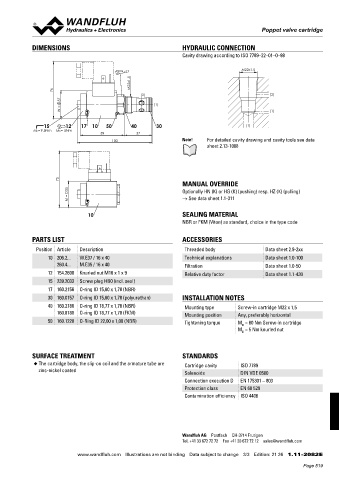
DIMENSIONS HYDRAULIC CONNECTION
Cavity drawing according to ISO 7789–22–01–0–98
M22x1.5
s27
M22x1.5
76
(2) (2)
37
(1)
W = (1)
15 12 17 10 50 40 30 (1)
MD=9.5Nm MD= 5Nm
59 37
100 Note! For detailed cavity drawing and cavity tools see data
sheet 2.13-1008
75
MANUAL OVERRIDE
35 Optionally HN (K) or HG (K) (pushing) resp. HZ (K) (pulling)
M = → See data sheet 1.1-311
10 SEALING MATERIAL
NBR or FKM (Viton) as standard, choice in the type code
PARTS LIST ACCESSORIES
Position Article Description Threaded body Data sheet 2.9-2xx
10 206.2... W.E37 / 16 x 40 Technical explanations Data sheet 1.0-100
260.4... M.E35 / 16 x 40 Filtration Data sheet 1.0-50
12 154.2600 Knurled nut M16 x 1 x 9 Relative duty factor Data sheet 1.1-430
15 239.2033 Screw plug HB0 (incl. seal)
17 160.2156 O-ring ID 15,60 x 1,78 (NBR)
30 160.0157 O-ring ID 15,60 x 1,78 (polyurethan) INSTALLATION NOTES
40 160.2188 O-ring ID 18,77 x 1,78 (NBR) Mounting type Screw-in cartridge M22 x 1,5
160.8188 O-ring ID 18,77 x 1,78 (FKM) Mounting position Any, preferably horizontal
50 160.1220 O-Ring ID 22,00 x 1,00 (NBR) Tightening torque M = 60 Nm Screw-in cartridge
D
M = 5 Nm knurled nut
D
SURFACE TREATMENT STANDARDS
◆ The cartridge body, the slip-on coil and the armature tube are Cartridge cavity ISO 7789
zinc-nickel coated Solenoids DIN VDE 0580
Connection execution D EN 175301 – 803
Protection class EN 60 529
Contamination efficiency ISO 4406
Wandfluh AG Postfach CH-3714 Frutigen
Tel. +41 33 672 72 72 Fax +41 33 672 72 12 [email protected]
www.wandfluh.com Illustrations are not binding Data subject to change 3/3 Edition: 21 26 1.11-2082 E
Page 519