Page 550 - Softbound_Edition_19_en
P. 550

Poppet valve
                                                                                                Poppet valve                                                                                                                 Poppet valve


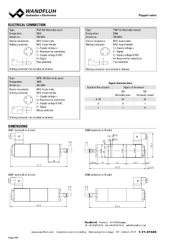
       ELECTRICAL CONNECTION                                                                                                       Solenoid operated poppet valve with additional
                                                                                                                                   inductive switching position monitoring              NG6
       Type:              PNP, NO (Normally open)           Type:              PNP, NC (Normally closed)                                                                                ISO 4401-03
       Designation:       Z603                              Designation:       Z482                                                Flange construction
       Article no.:       205.5024                          Article no.:       205.5023                                             ◆  2/2- and 3/2-way
       Device receptacle  M12, 4 pole male                  Device receptacle  M12, 4 pole male                                     ◆  normally open and normally closed
       Mating connector   M12, 4 pole female                Mating connector   M12, 4 pole female                                   ◆  Q  = 40 l/min
                                                                                                                                       max
                          1 = Supply voltage +                                 1 = Supply voltage +                                 ◆  p   = 350 bar
                   2  1                                                2   1                                                           max
                          2 = Reserved for extentions                          2 = Signal
                   3  4                                                3  4
                          3 = Supply voltage 0 VDC                             3 = Supply voltage 0 VDC
                   1      4 = Signal                                    1      4 = Reserved for extentions                         DESCRIPTION
                   4      Plus switched                                 2      Plus switched                                       Solenoid operated poppet valve according to data sheet 1.11-2140
                   3                                                    3
                                                                                                                                   with additional inductive switching position monitoring. The cont-
       Mating connector not included in delivery            Mating connector not included in delivery                              actless sensor transmits the poppet position to a step signal.


       Type:              NPN, NO (Normally open)                                                                                  TYPE CODE
       Designation:       Z680                                              Signal characteristics                                  2/2 or 3/2 way execution                                                  A        2  06     -     -     #
       Article no.:       205.5026                           Signal of the actuator   Signal of the sensor
       Device receptacle  M12, 4 pole male                                                                                          International standard interface ISO
       Mating connector   M12, 4 pole female                                         NO             NC
                          1 = Supply voltage +                                  Normally open  Normally closed                      Solenoid, Medium                 M
                   2  1                                                                                                             Solenoid, Super                   S
                          2 = Reserved for extentions              A / B             S1             S1
                   3  4
                          3 = Supply voltage 0 VDC                  0                0              1                               2 way (connections)               2
                   1      4 = Signal                                1                1              0                               3 way (connections)               3
                   4      Minus switched
                   3                                                                                                                2 switching positions
       Mating connector not included in delivery                                                                                    Nominal size 6

                                                                                                                                    Normally closed             Solenoid on A-side       1a
       DIMENSIONS                                                                                                                   Normally open               Solenoid on B-side       0b
       22061 (solenoid on A side)                          22060 (solenoid on B side)
                                                                                                                                    Other type designation according to type code data sheet 1.11-2140
              A                                                                  9.5           B
                                                                                 5.5                                                Polarity /Signal output /Monitoring
                                                                          8                                                         PNP / NO or NC                   P1
                                                                                                           85.3                     NPN / NO                         P2

                                                                       45             46      45                                    Design index (subject to change)
                                                                          38
                                                                                                                                    1.11-2142
                                      39                                                                                           GENERAL SPECIFICATIONS                               ACCESSORIES
                                                                26.65    39       64          64.2     4
                           197.9                                                                                                    Weight             2,25 kg                           Mating connector (plug female)
                                                                                 197.9                   5.8                                                                             straight, screw terminal    Article no. 219.2978
                                                                                                                                    Sensor Specifications:
       32061 (solenoid on A side)                          32060 (solenoid on B side)                                                                                                    90°, screw terminal         Article no. 219.3003
                                                                                                                                    Operating voltage  10…36 VDC
             A                                                                                 B                                    Signal current     max. 200 mA
                                                                                                                                                       IP 68                              SURFACE TREATMENT
                                                                                                                                                       According to the connection type, the
                                                                                                                                    Protection class                                      ◆  The valve body is painted with a two component paint
                                                                                                                                                       protection class of the valve can be   ◆  The solenoid, the flange and the cover are zinc-nickel coated
                                                                                                                                                       lower, see data sheet 1.11-2140
                                                                                                                                                                                          ◆  The socket head screws are zinc coated
                                                                                                                                    Dimensions         M12 x 1
                          197.9                                                  197.9                                              Ambient temperature  -25…+70 °C
                                                                                                                                    Fastening torque   7,5 Nm                             Note!   Other specifications, see data sheet 1.11-2140


                                                           Wandfluh AG  Postfach  CH-3714 Frutigen
                                                           Tel. +41 33 672 72 72  Fax +41 33 672 72 12  [email protected]

                       www.wandfluh.com  Illustrations are not binding  Data subject to change  2/2  Edition: 21 01  1.11-2142 E                   www.wandfluh.com  Illustrations are not binding  Data subject to change  1/2  Edition: 22 37  1.11-2143 E
       Page 550
   545   546   547   548   549   550   551   552   553   554   555