
Page 558 - Softbound_Edition_19_en
P. 558
Poppet valve
Poppet valve Poppet valve
ELECTRICAL SPECIFICATIONS HYDRAULIC SPECIFICATIONS VALVES INSTALLED
Protection class IP65 Working pressure Medium: p = 160 bar The central functioning element is the poppet valve cartridge NG6, data sheet 1.11-2030.
max
Relative duty factor 100 % DF Super: p = 350 bar
max
Switching frequency 15'000 / h Maximum volume flow Q = 40 l/min, see characteristic DIMENSIONS HYDRAULIC CONNECTION
max
Service life time 10 (number of switching cycles, Volume flow direction Any (see characteristic) 4/3-way
7
theoretically) Leakage oil Seat tight, max. 0,05 ml / min (approx. 1 30 35 17.8
Voltage tolerance ± 10 % with regard to nominal voltage drop / min) at 30 cSt A MD=5.2Nm 9.5 B T
Standard nominal 12 VDC, 24VDC, 115 VAC, 230 VAC Fluid Mineral oil, other fluid on request 8 5.5
voltage AC = 50 to 60 Hz, rectifier integrated in Viscosity range 12 mm /s…320 mm /s 31 A B 21 32.5
2
2
the connector socket Temperature range -20…+70 °C E E
fluid 131 P
Note! Other electrical specifications see data sheet 1.1-122 21.5
(Medium) and 1.1-127 (Super) Contamination Class 20 / 18 / 14 91 92 84 40.5
efficiency E E
Filtration Required filtration grade ß 10…16 ≥ 75,
see data sheet 1.0-50 PARTS LIST
20 50 10 70
PERFORMANCE SPECIFICATIONS MD=9.5Nm 4 64 72 Position Article Description
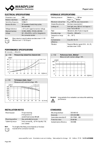
Oil viscosity u = 30 mm /s 220 10 260.64.. Solenoid SIN45DV-…-M40-HB0
2
∆p = f (Q) Pressure drop volume flow characteristic p = f (Q) Performance limits „Medium” 260.74.. Solenoid SIS45DV-…-M40-HB0
Measured with nominal voltage -10% 30 219.2001 Electric plug A (grey)
p [bar] 46
50 K0584 P B / P A p [bar] 35 219.2002 Electric plug B (black)
40 200 K0077 50 246.2171 Socket head screw M5 x 70 DIN 912
A E = Air bleed screw
T / B T
30 150 70 160.2093 O-ring ID 9,25 x 1,78 (NBR)
20 100 160.6092 O-ring ID 9,25 x 1,78 (FKM)
10
50
0
0 5 10 15 20 25 30 35 40 Q [l/min] 0 ACCESSORIES SURFACE TREATMENT
0 5 10 15 20 25 30 35 40 Q [l/min] Fixing screws Data sheet 1.0-60 ◆ The valve body is painted with a two component paint
Threaded subplates Data sheet 2.9-05 ◆ The solenoid is zinc coated
p = f (Q) Performance limits „Super” ◆ The screws are zinc coated
Measured with nominal voltage -10% Multi-station subplates Data sheet 2.9-45
Horizontal mounting blocks Data sheet 2.9-85
p [bar] P B / A T SEALING MATERIAL
A / B T
350 K0583 P Technical explanations Data sheet 1.0-100 NBR or FKM (Viton) as standard, choice in the type code
300 Hydraulic fluids Data sheet 1.0-50
250
200 Filtration Data sheet 1.0-50
150 Relative duty factor Data sheet 1.1-430
100
50 Attention! Long periods of non-actuation can reduce the switching
0 performance
0 5 10 15 20 25 30 35 40 Q [l/min]
INSTALLATION NOTES STANDARDS
Mounting type Flange mounting Mounting interface ISO 4401-03
4 fixing holes for Solenoids DIN VDE 0580
socket head screws M5 x90 Connection execution D EN 175301 – 803
Mounting position Any, preferably horizontal Protection class EN 60 529
Tightening torque Fixing screws M = 9,7 Nm (quality 12.9, Contamination efficiency ISO 4406
D
zinc coated)
Note! The length of the fixing screw depends on the base
material of the connection element.
Wandfluh AG Postfach CH-3714 Frutigen
Tel. +41 33 672 72 72 Fax +41 33 672 72 12 [email protected]
www.wandfluh.com Illustrations are not binding Data subject to change 2/3 Edition: 17 20 1.11-2150 E www.wandfluh.com Illustrations are not binding Data subject to change 3/3 Edition: 17 20 1.11-2150 E
Page 558