
Page 579 - Softbound_Edition_19_en
P. 579
Solenoid operated poppet valve
Poppet valve
PERFORMANCE SPECIFICATIONS
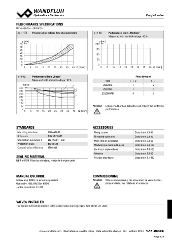
Oil viscosity u = 30 mm /s
2
Δp = f (Q) Pressure drop volume flow characteristics p = f (Q) Performance limits „Medium”
Measured with nominal voltage -10 %
p [bar] p [bar]
35 K0078 200 K0077
30
25 150
20 100
15
10 50
5
0 0
0 5 10 15 20 25 30 35 40 Q [l/min] 0 5 10 15 20 25 30 35 40 Q [l/min]
p = f (Q) Performance limits „Super” Flow direction
Measured with nominal voltage -10 % Type 1 → 2 2 → 1
p [bar] 4 1 ZS22061. 1 2
350 K0257 2 ZS22060. 1 3
300 5
250 3 ZS22060AB 4 5
200
150
100
50 Attention! Long periods of non-actuation can reduce the switching
0 performance
0 5 10 15 20 25 30 35 40 Q [l/min]
STANDARDS ACCESSORIES
Mounting interface ISO 4401-03 Fixing screws Data sheet 1.0-60
Solenoids DIN VDE 0580 Threaded subplates Data sheet 2.9-30
Connection execution D EN 175301 – 803 Multi-station subplates Data sheet 2.9-60
Protection class EN 60 529 Module type manifold blocks Data sheet 2.9-100
Contamination efficiency ISO 4406
Technical explanations Data sheet 1.0-100
Filtration Data sheet 1.0-50
SEALING MATERIAL Relative duty factor Data sheet 1.1-430
NBR or FKM (Viton) as standard, choice in the type code
MANUAL OVERRIDE COMMISSIONING
Screw plug (HB0), no actuation possible Attention! When commissioning, the valve must be vented under
Optionally: HB6, HN(K) or HR(K) pressure (max. two rotations of screw E).
→ See data sheet 1.1-311
VALVES INSTALLED
The central functioning element is the poppet valve cartridge NG6, data sheet 1.11-2030.
www.wandfluh.com Illustrations are not binding Data subject to change 3/4 Edition: 20 44 1.11-2540 E
Page 579