
Page 612 - Softbound_Edition_19_en
P. 612
Poppet valve
Poppet valve Poppet valve
DIMENSIONS Solenoid operated poppet valve stainless
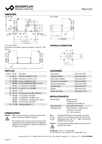
3/2-; 2/2-way 3/2-; 2/2-way NG6
Flange construction ISO 4401-03
110 9.5 ◆ 2/2- or 3/2-way
5.5 MD=5.2Nm ◆ normally open and normally closed x II 2 G Ex db IIC T6, T4
8 ◆ Q = 40 l/min x II 2 D Ex tb III C T80 °C, T130 °C
max
94 p = 350 bar
E ◆ max x I M2 Ex db I Mb
45 46 Class I Division 1
23 15 38 Class I Zone 1
12 17 18 10 18 70 40 60 10
MD= 9Nm MD= 5.2Nm 64
60 8
91 64 15 171 AEXd22060b DESCRIPTION APPLICATION
171 AEXd32060b
156 AEXd22061a Direct operated 2/2- and 3/2-way poppet valve in flange construc- These valves are suitable for applications in explosion-hazard
171 AEXd32061a tion. By means of the pressure tight switching solenoid, the poppet areas, open cast and also in mines. The stainless execution is
E = Air bleed screw HYDRAULIC CONNECTION valve spool is opened or closed acting against the spring.Due to the especially suitable for the use in wet and salty environment.Poppet
Dimensions of the solenoid coil see data sheet 1.1-183 and 1.1-184 poppet spool construction with pressure compensation on both valves are used where tight closing functions of the valve are
3/4-way 17.8 sides, the flow through the valve is possible in both directions. The essential like leakage-free load holding, clamping or gripping.
metallically sealing seat closes the valve virtually leak free. The
T
pressure tight encapsulated Ex-protection solenoid coil prevents
A B an explosion on the inside penetrating to the outside as well as an
31 21 32.5 ignitable surface temperature.
P
21.5
40.5 CERTIFICATES ACTUATION
10 Surface Mining Standard Z604 Actuation Switching solenoid, wet pin push type,
274
-25 °C to… -40 °C to… pressure tight
PARTS LIST ACCESSORIES ATEX x x x x Execution MKY45 / 18x60 (data sheet 1.1-183)
Position Article Description Fixing screws Data sheet 1.0-60 IECEx x x x x MKU45 / 18x60 (data sheet 1.1-184)
10 263.6... Solenoid coil MK.45 / 18 x 60 Threaded subplates Data sheet 2.9-05 CCC x x x x Connection Cable gland for cable Ø 6,5…14 mm
12 154.2603 Knurled nut Ex M18 x 1,5 x 18 Multi-station subplates Data sheet 2.9-45 EAC x x x x Attention! The UL execution is always supplied without cable
15 239.2033 Screw plug HB0 (incl. seal) Horizontal mounting blocks Data sheet 2.9-85 Australia x x x x gland
239.2043 Screw plug HB0-H40-Z591 (incl. seal) Technical explanations Data sheet 1.0-100 MA x x
17 160.2251 O-ring ID 25,07 x 2,62 (NBR) Hydraulic fluids Data sheet 1.0-50 UL / CSA x x x
18 160.2170 O-ring ID 17,17 x 1,78 (NBR) Filtration Data sheet 1.0-50 The certificates can be found on www.wandfluh.com
40 058.4215 Cover Relative duty factor Data sheet 1.1-430 STANDARDS
60 246.2117 Socket head screw M5 x 16 DIN 912 Explosion protection Directive 2014 / 34 / EU (ATEX)
Flameproof enclosure EN / IEC / UL 60079-1, 31
70 160.2093 O-ring ID 9,25 x 1,78 (NBR) INSTALLATION NOTES
160.7092 O-ring ID 9.25 x 1,78 (NBR -40 °C) Cable entry EN 60079-0, 1, 7, 15, 31
160.0091 O-ring ID 9,25 x 1,78 (Polyurethan -60 °C) Mounting type Flange mounting Mounting interface ISO 4401-03
160.6092 O-ring ID 9.25 x 1,78 (FKM) 4 fixing holes for Protection class EN 60 529
110 111.1080 Cable gland M20 x 1,5 socket head screws M5 x 45 Contamination ISO 4406
Mounting position Any, preferably horizontal efficiency
Tightening torque Fixing screws M = 5,2 Nm (screw
D
quality 8.8, zinc coated)
COMMISSIONING M = 5 Nm knurled nut
D
Attention! When commissioning, the valve must be vented under Note! The length of the fixing screw depends on the base SYMBOL
pressure (max. two rotations of screw E). material of the connection element. For valves for the A.22060b A.22061a A.32060b A.32061a
temperature range „-60 °C to…” (Z591), screws of the A A A A
The solenoid coil must only be put into operation, if the quality A4 have to be used.
requirements of the operating instructions supplied are Attention! For stack assembly please observe the remarks in the a a b b a a b b a a b b a a b b
observed to their full extent. In case of non-observance, operating instructions P P P T P T
no liability is assumed.
Wandfluh AG Postfach CH-3714 Frutigen
Tel. +41 33 672 72 72 Fax +41 33 672 72 12 [email protected]
www.wandfluh.com Illustrations are not binding Data subject to change 4/4 Edition: 21 18 1.11-3143 E www.wandfluh.com Illustrations are not binding Data subject to change 1/4 Edition: 21 18 1.11-3143S E
Page 612