
Page 599 - Softbound_Edition_19_en
P. 599
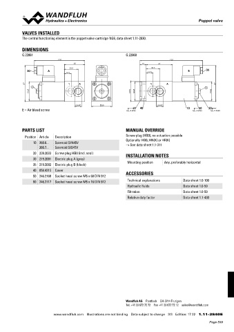
G.2206
                                                                                                      Poppet valve


            VALVES INSTALLED
            The central functioning element is the poppet valve cartridge NG6, data sheet 1.11-2030.


            DIMENSIONS
            G.22061                                              G.22060
                               124                                                      153
                                       50                                 15      64
                                     33.5                                      33.5
               30        A                                                                       B        35
                                   16.5                                      16.5

               87                                                                                               87
                 E                                                                                        E
                45                                                 50   45                                   45


                                        G3/8"         50                          G3/8"
                                                                     60
                                                                                                      50
            E = Air bleed screw                                  MD=5.2Nm  40                   10  MD=5.2Nm  20 MD=9.5Nm


            PARTS LIST                                           MANUAL OVERRIDE

              Position Article  Description                      Screw plug (HB0), no actuation possible
                                                                 Optionally: HB6; HN(K) or HR(K)
                  10 260.6...  Solenoid SIN45V                   → See data sheet 1.1-311
                     260.7...  Solenoid SIS45V
                  20 239.2033  Screw plug HB0 (incl. seal)       INSTALLATION NOTES
                  30 219.2001  Electric plug A (grey)
                                                                  Mounting position  Any, preferably horizontal
                  35 219.2002  Electric plug B (black)
                  40 058.4215  Cover
                  50 246.2160  Socket head screw M5 x 60 DIN 912  ACCESSORIES
                  80 246.2117  Socket head screw M5 x 16 DIN 912  Technical explanations      Data sheet 1.0-100
                                                                  Hydraulic fluids            Data sheet 1.0-50
                                                                  Filtration                  Data sheet 1.0-50
                                                                  Relative duty factor        Data sheet 1.1-430


                                                                 Wandfluh AG  Postfach  CH-3714 Frutigen
                                                                 Tel. +41 33 672 72 72  Fax +41 33 672 72 12  [email protected]

                            www.wandfluh.com  Illustrations are not binding  Data subject to change  3/3  Edition: 17 22  1.11-2840 E
                                                                                                            Page 599