
Page 594 - Softbound_Edition_19_en
P. 594
G.2204
Poppet valve G.2204
GENERAL SPECIFICATIONS HYDRAULIC SPECIFICATIONS VALVES INSTALLED
Designation 2/2-way poppet valve Working pressure Medium: p = 160 bar Zentrales Funktionselement ist die Sitzventilpatrone NG4, Datenblatt 1.11-2020.
max
Construction Direct operated Super: p = 350 bar DIMENSIONS
max
Mounting Installation in pipes Maximum volume flow Q = 15 l/min, see characteristic G.22041 G.22040
max
Nominal size NG4 Volume flow direction Any (see characteristic) 115 134
Connection Threaded connection G1/4“ Leakage oil Seat tight, max. 0,05 ml / min (approx. 1 45 10 54
Actuation Switching solenoid drop / min) at 30 cSt 30 A 29.5 29.5 B 35
Ambient temperature -25…+70 °C (NBR) Fluid Mineral oil, other fluid on request 16.3 16.3
2
2
-20…+70 °C (FKM) Viscosity range 12 mm /s…320 mm /s
Weight ≤ 1,2 kg Temperature range -20…+70 °C 78 E 82
MTTFd 150 years fluid 35 42 50 35 E 35
Contamination Class 20 / 18 / 14
efficiency
ELECTRICAL SPECIFICATIONS Filtration Required filtration grade ß 10…16 ≥ 75, G1/4" 50 G1/4"
Protection class IP65 see data sheet 1.0-50 E = Air bleed screw 60 40 10 50 20
MD= 2.6Nm MD= 2.6Nm MD=9.5Nm
Relative duty factor 100 % DF
Switching frequency 15'000 / h
Service life time 10 (number of switching cycles, STANDARDS PARTS LIST MANUAL OVERRIDE
7
theoretically) Solenoids DIN VDE 0580 Position Article Description Screw plug (HB0), no actuation possible
Voltage tolerance ± 10 % with regard to nominal voltage Connection execution D EN 175301 – 803 10 260.4... Solenoid SIN35V Optionally: HB4,5; HN(K) or HR(K)
Standard nominal 12 VDC, 24VDC, 115 VAC, 230 VAC 260.5... Solenoid SIS35V → See data sheet 1.1-311
voltage AC = 50 to 60 Hz, rectifier integrated in Protection class EN 60 529
the connector socket Contamination efficiency ISO 4406 20 239.2033 Screw plug HB0 (incl. seal) INSTALLATION NOTES
30 219.2001 Electric plug A (grey)
Note! Other electrical specifications see data sheet 1.1-105 35 219.2002 Electric plug B (black) Mounting position Any, preferably horizontal
(Medium) and 1.1-110 (Super)
40 056.4201 Cover ACCESSORIES
50 246.1161 Socket head screw M4 x 60 DIN 912
SEALING MATERIAL SURFACE TREATMENT 60 246.1113 Socket head screw M4 x 12 DIN 912 Technical explanations Data sheet 1.0-100
NBR or FKM (Viton) as standard, choice in the type code ◆ The valve body, the solenoid, the cover and the socket head Hydraulic fluids Data sheet 1.0-50
srews are zinc coated Filtration Data sheet 1.0-50
Relative duty factor Data sheet 1.1-430
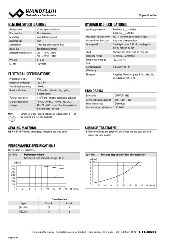
PERFORMANCE SPECIFICATIONS
Oil viscosity u = 30 mm /s
2
p = f (Q) Performance limits Δp = f (Q) Pressure drop volume flow characteristics
Measured with nominal voltage -10 % p [bar]
p [bar] 2 1 14 K0161
350 K0160 12
300 10
250 8
200 3 6
150 4
100 2
50 0
0 0 2 4 6 8 10 12 14 16 Q [l/min]
0 2 4 6 8 10 12 14 16 Q [l/min]
Flow direction
Type P → A A → P
GM2204. 3 3
GS2204. 1 2
Wandfluh AG Postfach CH-3714 Frutigen
Tel. +41 33 672 72 72 Fax +41 33 672 72 12 [email protected]
www.wandfluh.com Illustrations are not binding Data subject to change 2/3 Edition: 17 22 1.11-2820 E www.wandfluh.com Illustrations are not binding Data subject to change 3/3 Edition: 17 22 1.11-2820 E
Page 594