
Page 590 - Softbound_Edition_19_en
P. 590
Solenoid operated poppet valve Solenoid operated poppet valve
Poppet valve
TYPE CODE PERFORMANCE SPECIFICATIONS
2
Z 2 2 10 - - # Oil viscosity u = 30 mm /s
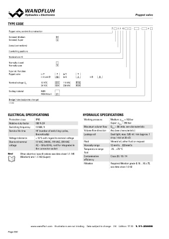
Poppet valve, sandwich construction Δp = f (Q) Pressure drop volume flow characteristics p = f (Q) Leistungsgrenzen «Medium»
Gemessen mit Nennspannung -10 %
Solenoid, Medium M
Solenoid, Super S p [bar] p [bar] 2 4 3 1
20 K0157 175 K0362
2 way (connections) 150
15 125
2 switching positions 100
10 75
Nominal size 10
5 50
25
Normally closed 1 0 0
Normally open 0 0 10 20 30 40 50 60 70 80 Q [l/min] 0 10 20 30 40 50 60 70 80 Q [l/min]
Type list / Function
Poppet valve in P P in T T
in A and B AB in A A in B B p = f (Q) Performance limits „Super” Flow direction
Measured with nominal voltage -10 % Type 1 → 2 2 → 1
Nominal voltage U N 12 VDC G12 115 VAC R115
24 VDC G24 230 VAC R230 p [bar] Z.22101. 1 2
350 K0363 1 Z.22100. 1 3
Sealing material NBR 300
FKM (Viton) D1 250 3 Z.22100AB 1 4
200 2
Design index (subject to change) 150 4
1.11-2560 100
50 Attention! Long periods of non-actuation can reduce the switching
0 performance
0 10 20 30 40 50 60 70 80 Q [l/min]
ELECTRICAL SPECIFICATIONS HYDRAULIC SPECIFICATIONS
Protection class IP65 Working pressure Medium: p = 160 bar STANDARDS ACCESSORIES
max
Relative duty factor 100 % DF Super: p = 350 bar Mounting interface ISO 4401-05 Fixing screws Data sheet 1.0-60
max
Switching frequency 15'000 / h Maximum volume flow Q = 80 l/min, see characteristic Solenoids DIN VDE 0580 Threaded subplates Data sheet 2.9-05
max
Service life time 10 (number of switching cycles, Volume flow direction Any (see characteristic) Connection execution D EN 175301 – 803 Multi-station subplates Data sheet 2.9-45
7
theoretically) Leakage oil Seat tight, max. 0,05 ml / min (approx. 1 Protection class EN 60 529
Voltage tolerance ± 10 % with regard to nominal voltage drop / min) at 30 cSt Contamination efficiency ISO 4406 Horizontal mounting blocks Data sheet 2.9-85
Standard nominal 12 VDC, 24VDC, 115 VAC, 230 VAC Fluid Mineral oil, other fluid on request Technical explanations Data sheet 1.0-100
2
2
voltage AC = 50 to 60 Hz, rectifier integrated in Viscosity range 12 mm /s…320 mm /s MANUAL OVERRIDE Hydraulic fluids Data sheet 1.0-50
the connector socket Temperature range -20…+70 °C Filtration Data sheet 1.0-50
fluid Screw plug (HB0), no actuation possible Relative duty factor Data sheet 1.1-430
Note! Other electrical specifications see data sheet 1.1-145 Optionally: HB8,5, HN(K) or HR(K)
(Medium) and 1.1-150 (Super) Contamination Class 20 / 18 / 14 → See data sheet 1.1-311
efficiency
Filtration Required filtration grade ß 10…16 ≥ 75, SEALING MATERIAL COMMISSIONING
see data sheet 1.0-50 NBR or FKM (Viton) as standard, choice in the type code Attention! When commissioning, the valve must be vented under
pressure (max. two rotations of screw E).
SURFACE TREATMENT INSTALLATION NOTES
◆ The sandwich bodies made of steel are zinc-phosphated Mounting type Sandwich mounting
◆ The solenoid and the cover are zinc coated 4 fixing holes for
◆ The socket head screws are zinc coated socket head screws or studs M6
Mounting position Any, preferably horizontal
Tightening torque Fixing screws M = 8,9 Nm (quality 8.8,
D
zinc-coated)
VALVES INSTALLED
The central functioning element is the poppet valve cartridge NG10, data sheet 1.11-2040.
www.wandfluh.com Illustrations are not binding Data subject to change 2/4 Edition: 17 33 1.11-2560 E www.wandfluh.com Illustrations are not binding Data subject to change 3/4 Edition: 17 33 1.11-2560 E
Page 590