
Page 486 - Softbound_Edition_19_en
P. 486
Poppet valve
Poppet valve cartridge Poppet valve
GENERAL SPECIFICATIONS HYDRAULIC SPECIFICATIONS PERFORMANCE SPECIFICATIONS
2
Designation 2/2-, 3/2-way poppet valve Working pressure p = 350 bar Oil viscosity u = 30 mm /s
max
Construction Direct operated Maximum volume flow Q = 40 l/min, see characteristics p = f (Q) Performance limit FG Flow direction
max
Mounting Screw-in cartridge construction Leakage oil Seat tight, max. 0,15 ml / min (approx. 3 Measured with nominal voltage -10% Execution 1 → 2 2 → 1 2 → 3 3 → 2
Nominal size M22 x 1,5 according to ISO 7789 drops / min) at 30 cSt p [bar] SDSPM22-FG 2 1 1 3
Actuation Switching solenoid Fluid Mineral oil, other fluid on request 350 K4192
Ambient temperature -25…+70 °C Viscosity range 12 mm /s…320 mm /s 300 3 2
2
2
Weight 0,56 - 0,60 kg Temperature range -25…+70 °C (NBR) 250 1
200
MTTFd 150 years fluid -20…+70 °C (FKM) 150
Contamination Class 20 / 18 / 14 100
efficiency 50
Filtration Required filtration grade ß 10…16 ≥ 75, 0 0 2.5 5 7.5 10 12.5 15 17.5 20 Q [l/min]
see data sheet 1.0-50
ELECTRICAL SPECIFICATIONS ACTUATION ∆p = f (Q) Pressure drop volume flow characteristics Flow direction
Protection class Connection execution D: IP65 Actuation Switching solenoid, wet pin push type, p [bar] Execution 1 → 2 2 → 1 2 → 3 3 → 2
Connection execution J: IP66 pressure tight 40 K4193 SDSPM22-AB 3 4 - -
Connection execution G: IP67 and IP69K Execution V.E37 / 19 x 50 (Data sheet 1.1-168) 35 1 SDSPM22-BA 2 2 - -
Relative duty factor 100 % DF N.S35 / 19 x 50 (Data sheet 1.1-175) 30 2 SDSPM22-FG 3 4 1 1
25
Switching frequency 5'000 / h Connection Connector socket EN 175301 – 803 20
Service life time 10 (number of switching cycles, Connector socket AMP Junior-Timer 15 4
7
10
theoretically) Connector Deutsch DT04 – 2P 5 3
Voltage tolerance ± 10 % with regard to nominal voltage 0 0 5 10 15 20 25 30 35 40 Q [l/min]
Standard nominal 12 VDC, 24VDC, 115 VAC, 230 VAC
voltage AC = 50 to 60 Hz, rectifier integrated in Note! The switching times depend on the volume flow,
the connector socket Swichting times pressure and viscosity. In case of very large volume
Type Flow Switching on Switching off flows, the switching time for closing can get consider-
Note! Other electrical specifications see data sheet 1.1-168 direction ably longer.
(slip-on coil V) and 1.1-175 (slip-on coil N)
AB 1 → 2 approx. 40 ms approx. 20 ms
2 → 1 approx. 40 ms approx. 10 ms
SDSPM22 BA 1 → 2 approx. 30 ms approx. 30 ms
SURFACE TREATMENT SEALING MATERIAL 2 → 1 approx. 40 ms approx. 30 ms
◆ The cartridge body, the slip-on coil and the armature tube are NBR or FKM (Viton) as standard, choice in the type code FG 1 → 2 approx. 40 ms approx. 10 ms
zinc-nickel coated 2 → 1 approx. 40 ms approx. 10 ms
2 → 3 approx. 40 ms approx. 40 ms
3 → 2 approx. 40 ms approx. 20 ms
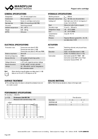
PERFORMANCE SPECIFICATIONS
Oil viscosity u = 30 mm /s
2
HYDRAULIC CONNECTION HYDRAULIC CONNECTION
p = f (Q) Performance limit AB / BA Flow direction Cavity drawing according to ISO 7789–22–01–0–98 Cavity drawing according to ISO 7789–22–04–0–98
Measured with nominal voltage -10% Execution 1 → 2 2 → 1
p [bar] SDSPM22-AB 4 2 M22x1.5 M22x1.5
350 K4191 3 SDSPM22-BA 3 1
300 4 2
250 (3)
200 1 (2)
150
100 (2)
50 (1)
0
0 5 10 15 20 25 30 35 40 Q [l/min] (1)
(1)
(1)
Note! For detailed cavity drawing and cavity tools see data Note! For detailed cavity drawing and cavity tools see data
sheet 2.13-1008 sheet 2.13-1004
www.wandfluh.com Illustrations are not binding Data subject to change 2/4 Edition: 20 05 1.11-2061 E www.wandfluh.com Illustrations are not binding Data subject to change 3/4 Edition: 20 05 1.11-2061 E
Page 486