Page 487 - Softbound_Edition_19_en
P. 487

Poppet valve
                                                                                             Poppet valve cartridge


            PERFORMANCE SPECIFICATIONS
            Oil viscosity u = 30 mm /s
                             2
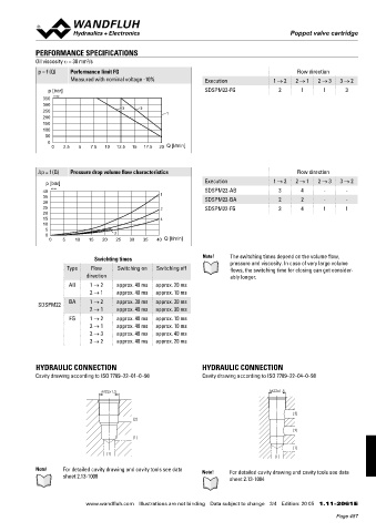
             p = f (Q)  Performance limit FG                                                   Flow direction
                       Measured with nominal voltage -10%         Execution             1 → 2  2 → 1  2 → 3  3 → 2
                p [bar]                                           SDSPM22-FG             2      1      1      3
               350  K4192
               300                      3    2
               250                                    1
               200
               150
               100
               50
                0
                 0   2.5  5   7.5  10  12.5  15  17.5  20  Q [l/min]


             ∆p = f (Q)  Pressure drop volume flow characteristics                             Flow direction

                p [bar]                                           Execution             1 → 2  2 → 1  2 → 3  3 → 2
               40  K4193                                          SDSPM22-AB             3      4       -      -
               35                                   1             SDSPM22-BA             2      2       -      -
               30
               25                                   2             SDSPM22-FG             3      4      1      1
               20
               15                                   4
               10
               5
               0                     3
                 0   5   10  15  20   25  30  35   40  Q [l/min]

                               Swichting times                   Note!    The switching times depend on the volume flow,
                      Type    Flow    Switching on  Switching off         pressure and viscosity. In case of very large volume
                                                                          flows, the switching time for closing can get consider-
                            direction                                     ably longer.
                       AB    1 → 2    approx. 40 ms  approx. 20 ms
                             2 → 1    approx. 40 ms  approx. 10 ms

             SDSPM22   BA     1 → 2   approx. 30 ms  approx. 30 ms
                              2 → 1   approx. 40 ms  approx. 30 ms
                       FG     1 → 2   approx. 40 ms  approx. 10 ms
                              2 → 1   approx. 40 ms  approx. 10 ms
                              2 → 3   approx. 40 ms  approx. 40 ms
                              3 → 2   approx. 40 ms  approx. 20 ms


            HYDRAULIC CONNECTION                                 HYDRAULIC CONNECTION
              Cavity drawing according to ISO 7789–22–01–0–98     Cavity drawing according to ISO 7789–22–04–0–98

                                  M22x1.5                                              M22x1.5


                                                                                              (3)
                                           (2)
                                                                                              (2)
                                           (1)
                                                                                              (1)
                                   (1)                                                  (1)

            Note!    For detailed cavity drawing and cavity tools see data   Note!  For detailed cavity drawing and cavity tools see data
                     sheet 2.13-1008                                      sheet 2.13-1004


                            www.wandfluh.com  Illustrations are not binding  Data subject to change  3/4  Edition: 20 05  1.11-2061 E
                                                                                                            Page 487
   482   483   484   485   486   487   488   489   490   491   492